Unique Methods and Techniques Fuel A New Maine Attraction
 |
| (Photo by Michael Goodman for ENR) |
Engineers with the Maine Dept. of Transportation refer to July 11, 2003, as “Black Friday.” It was the day they received a call informing them that an inspection of the Waldo-Hancock Bridge over the Penobscot River had revealed crucial strand breakages in a suspension cable.
While keeping the old steel bridge on U.S. Route 1 temporarily functional with a complex supplementary cable installation, MDOT now needed a fast-track process for its long-planned replacement (ENR 11/10/03 p. 24). “Our goal was to pour concrete by December of 2003” for a new bridge, recalls David Cole, MDOT commissioner.
In the interim five months, MDOT devised an owner-facilitated design-build process that amounted to an “arranged marriage” between designer and contractor, won over an “angst-ridden” community, and faced harsh criticism from steel bridge advocates. To top it all off, it would decide to go with a newly patented cable-cradle system that had never been installed on any bridge before.
 |
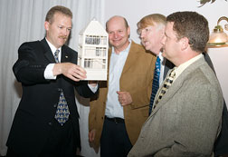
| Observing. Maine DOT officials, including Doe (third from left) and Cole (far right) admire model of bridge observatory. |
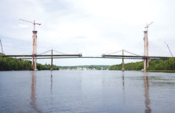
Three years later, the $84-million two-lane Penobscot Narrows Bridge and Observatory is moving toward a Christmas opening, with final completion in May 2007, says Tom Doe, MDOT project manager. That completion will include an elevator that will whisk visitors 420 ft up one pylon to a 13.5 x 24.5-ft glass-enclosed observatory. From this anticipated tourist destination, they will see sweeping vistas of the river, the nearby historic site of Fort Knox and the towns of Verona Island and Prospect (ENR 1/26/04 p. 15).
For the Maine joint venture of Pittsfield-based Cianbro Corp. and Woolwich-based Reed & Reed Inc., there were other firsts. “This was our first joint venture together,” says Archie Wheaton, Cianbro project superintendent. Moreover, it was their first cable-stayed, cast-in-place segmental job. The team also had to devise a method of lifting the 40 carbon steel cable cradles, up to 34 ft long with 16-in. diameters, into various locations within the two pylons. “It was scary, but we’ve done a lot of new things,” Wheaton says. “The biggest thing is trusting the design and the designer.”
 |
 |
| Cables. Cradles are set on steel frames for lifting into place within the pylon. (Photo by Michael Goodman for ENR) |
The designer, Tallahassee-based Figg Engineering Group, worked closely with the community to gain its trust as well, by conducting design charettes at meetings held in October 2003. The locals chose a look of granite as the theme for the bridge because it was “durable, natural and timeless,” notes Cheryl Maze, Figg director of lasting impressions. Moreover, it made contextual sense because the nearby 19th century-era Fort Knox military building is built of granite.
From five options, charette participants chose a slender single-plane design. MDOT had already determined that it wanted a cable-stayed bridge with cables within the deck center for ease of inspection. Moreover, the bridge type was ideal for the 1,161-ft main span needed to avoid foundations in the river. But it also wanted to transform the 420-ft height of the main tower, criticized by some, into an asset. So MDOT officials envisioned an obelisk-shaped observatory that would mimic the Washington Monument. The observatory, with which access roads and parking totaled about $5 million, was now possible because the cable cradle system saved space within the pylon and money within the budget.
 |
 |
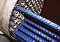
| Each strand runs through its own tube in the cheese plate. (Photo top courtesy of FIGG, bottom courtesy of Ohio DOT) |
W. Denney Pate, Figg principal engineer, estimates that his cable cradle system saves about $4 million because it eliminates the need for conventional anchorages. Each cradle contains a “cheese plate,” or a series of holes through which each cable strand passes, encased in stainless-steel tubes. It allows the stays to run continuously from the bridge deck through the pylon and back to the deck.
Dywidag-Systems International USA Inc., Bolingbrook, Ill., performed tests on stress forces in the stays and provided fabrication design for the cable-stayed installation and post-tensioning. DSI Chief Technology Officer Khaled Shawwaf notes that a few bridges already have cable saddles, “where all the strands go through and sit over one another.”
But “as the size of the cable gets larger, the strands on the top will squeeze the ones on the bottom,” he says. “The transverse stresses impact performance. The idea of the cable cradle is that since each strand has its own pipe, there is no bundle effect. In the future, should you wish to exchange a strand and pull one out, it will be easy. It’s almost impossible to do in the saddle.”
Each cradle, as heavy as 8,500 lb, was set into a steel supporting frame that accommodated its exact geometry, rotation and elevation, says Kaven Philbrook, Cianbro project manager. As crews jump-formed each pylon section, “we cast in steel embeds for a sole plate,” he says. A tower crane lifted the frame holding the cradle and sets it onto the sole plate, with 1⁄4-in. tolerances. Then the pylon section is finished off. Setting one cradle took half an hour.
After that, crews began running the 0.6-in.-dia, epoxy-coated strands between deck and pylon, and stressing them. “The first strand is the ‘master’ and you have to match it each time,” says Wheaton. “So by the last strand it’s totally uniform. The first strand is stressed higher than necessary because it decreases as more strands are stressed.” The total design force for stressing is 1,300 kips per cable.
Two main span segments, two back span segments and a stay equals one cycle, says Philbrook. “At the start, a cycle was taking 16 days with a schedule of 12. We added a small crew at night to work on critical activities. This brought our cycle time down to the 12-day cycle. Once we learned and refined the process, we have consistently made the four segments and stay installation in 10 days.”
For MDOT inspectors, future ease of inspection is a significant factor. “It was not easy to inspect the intertwining cables [of the old bridge],” says Cole. “The cables were encased in steel sheaths that actually kept moisture in.” Using mallets to inspect cables out in public was not a comforting sight, he adds. On the new bridge, an inspector can go into the pylon and inspect out of the public eye.
MDOT also went to extra lengths to avoid future corrosion problems. Pressurized inert gas will flow in spaces between each strand and outer sheaths of the strands, made of high-density polyethylene. Monitors on each stay will record deviation from 2-psi pressure and reservoir tanks will recharge gas.
 |
| Partnering. Figg’s Pate and Burgess (far left, second from right) chat with contractor joint venture officials Wheaton and Philbrook. (Photo by Michael Goodman for ENR) |
The superstructure now is almost complete. Each of the 91 main span segments averages 12 ft long and 57 ft wide. “We have four travelers for two pairs of segments launching from each pylon in each direction” for a total of 181 segments, says Greg Letourneau, Reed & Reed superintendent.
The upper portions of the tapered 14-ft-wide pylons are cast in 15.5-ft lifts with a jump form system. The Verona footing is on 288 driven steel piles to depths of 16 ft. The pylon with the observatory sits on a 80 x 70-ft spread footing, 16 ft deep, says Figg project manager Chris Burgess.
Contracts
From the beginning, every aspect of the project delivery process was streamlined. In selecting the designer by late July 2003, “we allowed only 10 pages for each design proposal” says Doe. Then, competing contracting teams priced out the conceptual design, followed by a back-and-forth through November 2003, says Doe. Two MDOT engineers and three Federal Highway Administration engineers scored the two competing team proposals on experience, quality, schedule, an interview, and estimated unit prices based upon the conceptual design.
|
The Cianbro/Reed&Reed team won a $56-million lump-sum contract that December, beating out a team led by Fru-Con Construction Corp., Ballwin, Mo. Fru-Con is building Ohio’s Maumee River Bridge, which also features the cable cradle system (see sidebar). Earlier, it had been awarded some $18 million of work for foundations and lower piles.
At the same time, MDOT went about securing a $50-million Guaranteed Anticipated Revenue bond, and a $4-million bond measure passed by voters in 2003. MDOT also convinced the governor to sign off on its accelerated owner-facilitated design-build plan. “We’d done design-build before, but we figured we’d modify the document,” says Doe. “Otherwise requests for proposals would take four months, and that would mean six to eight months before we could build. We didn’t want to wait.”
Philbrook praises the level of partnering between owner, designer and contractor. “If Tom [Doe] feels pain, I feel the pain,” he says.
There was certainly enough pain to go around. Early estimates from bidders were close to $105 million for the entire project, which MDOT had estimated at $75 million. The agency looked at dozens of different options for every single aspect of the design, remembers Cole. He cited the rising costs of fuel, concrete, steel and other materials.
MDOT and Figg also came under fire from Chicago-based National Steel Bridge Alliance, which objected to the Request for Proposals. NSBA Regional Director William F. McEleney says a public advisory committee in September 2003 had recommended a steel, dual-plane cable-stayed bridge that would be $25 million less than a cast-in-place concrete single-plane design. “Why was this impractical two-lane bridge type selected?” he asks.
 |
| Replace. Successor emerges alongside the aging and fragile Waldo-Hancock bridge. (Photo by Michael Goodman for ENR) |
Doe contends that the advisory committee did not consist of engineers with knowledge of long-term maintenance issues. He says that while a steel alternative may have been cheaper up-front, long-term maintenance issues balanced out the costs. For example, the geometry of a two-plane steel design would have increased the amount of plowed snow and salts hitting the cables, he says. Salty air would also increase maintenance for a steel bridge, he adds.
“I’d suggest it’s so far inland and high enough up that with reasonable maintenance, these should not be an issue,” counters McEleney. “But DOT got the bridge DOT wanted.”
What the contractor joint venture wants to do now is finish asphalt paving before winter hits, and in time for opening the bridge on Dec. 21 to traffic. “We’re right on schedule,” says Philbrook. By doing that and by clearing out of the site on May 7, 2007, the team will avoid $1,430 a day in late penalties.
When open, the new bridge will carry up to 18,000 daily motorists, many tourists heading for Bar Harbor in warm weather months. Members of a community once unhappy about the impending loss of its historic suspension bridge are now planning celebrations for the new “wicked good bridge,” including one on June 23, 2007.

