3D Model Plays Key Role In Modernizing Gallery
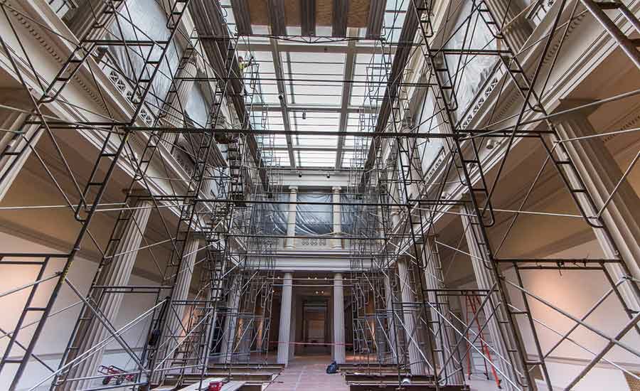
The project team was asked to modernize the former Corcoran Gallery of Art, a National Historic Landmark, but not affect its historic character.
PHOTO BY BRUCE BUCKLEY FOR ENR
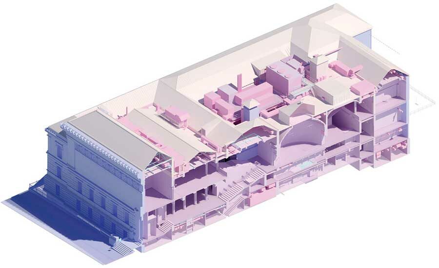
With limited asbuilts and original documents on hand, designers relied heavily on technology to recreate models of the historic structure.
IMAGE COURTESY OF LEO A DALY
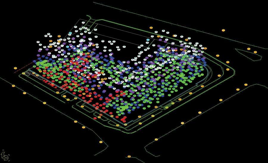
With limited asbuilts and original documents on hand, designers relied heavily on technology to recreate models of the historic structure.
IMAGE COURTESY OF LEO A DALY

Originally opened in 1897, the Beaux- Arts style building is currently undergoing a $50-million renovation slated to be completed early next year. The building will house National Gallery of Art exhibits as well as George Washington University’s Corcoran School of Art.
PHOTO COURTESY LEO A DALY
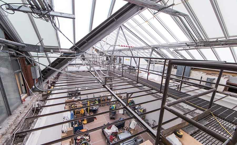
Due to stringent requirements for naturally lighting the second-floor galleries, the team creatively fit mechanical systems in the attic so they wouldn’t cast shadows into the space below.
PHOTO BY BRUCE BUCKLEY FOR ENR
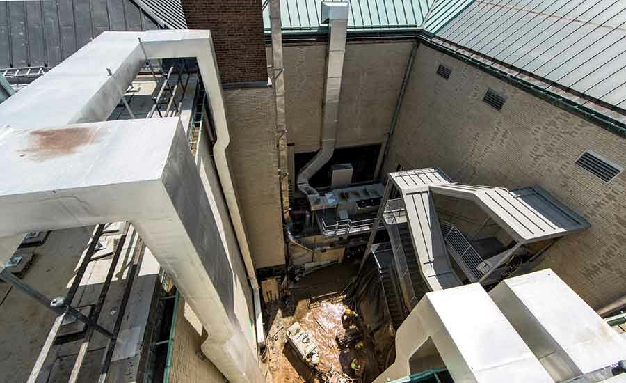
Unable to use a large mechanical penthouse, the team will infill a courtyard with MEP systems. The three-story courtyard will house four airhandling units, a generator and an egress stair tower for maintenance.
PHOTO BY BRUCE BUCKLEY FOR ENR


When the $50-million renovation of the former Corcoran Gallery of Art in Washington, D.C., began in early 2015, there was only a limited amount of original drawings and documentation about the building, a National Historic Landmark. But thanks to the design team’s extensive use of digital imaging, the Beaux Arts building is on full display to those working on the renovation. Tasked with preserving the 120-year-old building’s historic elements and determining how to best modernize its systems, the design team, led by Leo A Daly, used high-tech tools to create a detailed 3D model of the structure.
To provide an accurate view of the building, Leo A Daly, along with contractor Whiting-Turner and key consultants Mueller Associates and Silman, used multiple types of imaging techniques, including laser scanning, ground penetrating radar, CCT pipe camera surveying and hygrothermal wall analysis. Point clouds, created from laser scans, enabled the team to work much more efficiently, says Andrew Graham, associate architect at Leo A Daly. Graham estimates that the team’s data-gathering efforts enabled it to reduce site visits by at least 75%.
“We could pull it up on our screen with the team and take measurements of anything scanned,” Graham says. “We could survey rooms that we hadn’t thought of walking into. It helped us in the design of the [project] phases and figuring out solutions without spending a lot of time going there and writing down dimensions. It’s like we were virtually in the building.”
The strategy proved critical in solving many of the project’s most daunting challenges, such as fitting large modern mechanical systems in tight spaces and working with outdated, arcane structural elements.
After the Corcoran organization’s years of financial difficulties, the facility—a former museum and school of art—was acquired through an agreement with George Washington University and the National Gallery of Art in 2014. After the renovation is completed in 2018, GWU will use the facility for its art school. The updated building will include a separate entrance for students and include new teaching spaces converted from former storage spaces, display galleries and offices.
The NGA will use the building’s historic galleries to host traveling art and other exhibitions. NGA, in particular, has stringent requirements for air and light quality in the galleries.
Given those requirements and an overarching need to comply with current energy codes, the mechanical equipment specified to meet those goals was much larger than what had been used in the building, says Steve Gillis, principal and project manager with Mueller Associates, the mechanical and plumbing consultant on the project. “We were spatially challenged because of the historic nature of the building,” he says. “There was very limited space for MEP systems.”
The second-floor galleries are lit using a historic natural daylighting system. Skylights on the roof allow light into the attic spaces, which are diffused by a system of baffles before reaching “laylights” located on the attic floors and, at the same time, on the ceilings of the galleries below. Space is tight in the attic for mechanical equipment, because it could block light and create shadows in the galleries below.
Large mechanical penthouses also were not allowed on the roof because of a sightline easement held by a neighboring building.
In response, the team chose to infill a courtyard near the core of the building with mechanical equipment. The three-story courtyard—approximately 53 ft by 41 ft by 55 ft—will house four air-handling units, a generator and an egress stair tower to allow access for maintenance.
At grade level, a variable refrigerant flow system with heat recovery will serve the basement shop and academic spaces. It will also house dust-collection units for the metal and wood shops in the sub-basement. At the first level, three air-handling units with exhaust air energy recovery will serve the basement areas and condition the sub-basement shop spaces. At the second level, one large VAV-type air-handling unit with exhaust air energy recovery will serve first-floor academic and atrium spaces. A gas-fired emergency generator will be at the roof level.
“It’s built like a big Swiss watch,” Gillis says. “It’s like a big machine.”
Other infrastructure systems are strategically located in sub-basement spaces, concealed roof locations and within attics spaces that are outside of view.
Plumbing investigations also were a challenge, says Karen Schulte, plumbing engineer with Mueller. “We had limited existing documentation,” she says. “Some documents were made available to us of the original building, but the condition those drawings were in was partially faded or partially torn. We asked to have a pipe camera survey of the interiors of the pipes. That helped us determine where the piping is, the condition of the piping and how far below the slab is it. We were trying to get more information prior to the contractor going out and digging up the slab.”
The mechanical courtyard is on an independently supported platform. The team chose that option to avoid significant alterations to the building that would trigger the need for other structural upgrades, says Ryan Salmon, project engineer with Silman.
“What we ended up doing is creating a structural-steel platform that cantilevers out over the full footprint of the courtyard, but [it] is only founded on the upper corner of it,” Salmon says. “It’s supported by a deep foundation system—drilled micropiles over grade beams and steel structural frame. To fully fit the mechanical systems, it cantilevers twice as a double cantilever on the upper levels. It’s L-shaped but only supported on one corner.”
Structurally, the building also presented considerable unknowns. Salmon says the original building was constructed at a time when builders were experimenting with myriad floor systems.
The Corcoran used the Metropolitan System, which featured steel-framed units supported by twisted wire pairs that are spaced closely together. Around the wire pairs, the slab consists of a mixture of gypsum and wood chips. He says that the slab is “soft enough that you can carve through it with a spoon.”
Because of the floor systems, the team had concerns about structural integrity and fire ratings. “How do we deal with an esoteric, archaic system without damaging the historic fabric, but also understanding what we have there?” Salmon says. “We didn’t have any as-built drawings. One of our challenges was understanding what we had.”
A mix of modern technology and historic references were used to better understand the system. The team pored over engineering publications from the late 19th century to read up on fire-rating tests performed on the Metropolitan System. On site, the team used 3D ground-penetrating radar to reveal the core of the system. “It’s almost like a 3D X-ray,” he adds. “We got wire depth and spacing from that without having to open up the floor.”
Graham says the desire to create a “data ecosystem” on the project was driven, in part, by GWU. While Leo A Daly typically advocates the benefits of BIM for facilities management to clients, GWU officials already knew that they wanted to leverage the project data for future use.
“They came to us and said that they have a new facilities information management [FIM] guideline document and it was only a year old,” Graham says. “Essentially, it outlines how they would like to use BIM for their long-term facilities management. We have this FIM manual to guide us and they really understand what they will be getting from us.”


