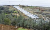
Oroville Team Passes Milestone, Presses on With Spillway Fix

Despite steep slopes, high temperatures and other hazards, crews with the general contractor have logged 770,000 hours on the spillway reconstruction without a recordable incident.
PHOTO BY FLORENCE LOW / CALIFORNIA DEPT. OF WATER RESOURCES

The new chute design rectifies numerous deficiencies found in the 1968 spillway.
SCHEMATIC COURTESY DWR

Water releases from the lake, due to record rains last winter, caused extensive damage to Oroville’s main spillway chute.
PHOTO COURTESY KIEWIT/CALIFORNIA DEPT. OF WATER RESOURCES

More than 600 workers rebuilt the spillway in 165 days—right up to the Nov. 1 deadline— to allow dam operators to use it in anticipation of the winter rainy season. However, work continues.
PHOTO COURTESY KIEWIT/CALIFORNIA DEPT. OF WATER RESOURCES


A mix of brute force and cutting-edge technology enabled contractors to replace a large portion of Oroville Dam’s spillway chute in just 165 days, meeting a Nov. 1 deadline set in anticipation of the start of northern California’s winter rainy season.
“We had to design and build a project in a nine-month period when it would normally be done in a 10-year period,” says Ted Craddock, project manager with the California Dept. of Water Resources. “We are extremely pleased with the work that’s been accomplished.”
The $500-million Lake Oroville Spillways Emergency Recovery Project rebuilds and strengthens the dam’s 3,055-ft-long spillway and adjacent emergency spillway, both damaged during record rainfall in February, when releases gouged an 1,100-ft-long, 200-ft-deep trench in the main spillway and undercut the emergency spillway.
After winning an accelerated bid in April, general contractor Kiewit Infrastructure West quickly mobilized an armada of equipment, concrete batch plants, crushing operations and workers to the 400-acre worksite. Crews began spillway work on May 20.
The project was divided into two phases because work on the main spillway is off-limits during the winter rainy season from December until May 2018. Phase one, completed in November, rebuilt two sections of reinforced, structural erosion-control concrete in an 870-ft-long upper chute section and a 350-ft-long lower section. Crews also placed some 350,000 cu yd of roller-compacted concrete (RCC) in the middle section where the washout had occurred.
Kiewit’s original contract, at the time of 30% design completion, was $275 million. Since that time, additional geotechnical investigation upped the amounts of excavation and materials required, which impacted the price. “It’s like when you go to the dentist and the cavity is bigger than you think—you have to remove all the bad stuff before you start filling it in,” says Jeff Petersen, Kiewit’s project director.
An independent forensic team’s interim report identified several potential causes for the damage to the original 1968 spillway, including a deficient drain system, thin concrete overlaying the drains, concrete with too little reinforcing steel and shallow anchors into low-quality rock. All of these deficiencies have been modified or changed in the new design, says Jeanne Kuttel, DWR incident commander.
The new structural concrete is placed in 30-ft-long, 37-ft-wide and 2.5-ft-thick blocks atop a course of leveling concrete about 5 ft thick, on average. Each block, reinforced with two layers of epoxy-coated 1-in. rebar—compared to just one layer of uncoated rebar in the 1968 spillway—is anchored to cleaned foundation rock via 14 anchor bolts to a depth of 15 ft to 25 ft. The old spillway used fewer bolts that penetrated only 5 ft. Two-ft to 5-ft-thick replacement walls rise between 20 ft and 34 ft high on the edges of the chute.
Inspection revealed some hairline cracks, which are being monitored. “The high early-strength concrete mix was designed to minimize shrinkage and cracking.
However, all concrete shrinks and cracks,” Petersen says. The cracks “are a normal part of the curing process for massive concrete that’s very restrained into the rock. These hairline cracks do not in any way affect the structural integrity of the spillway.”
For the middle section, crews placed RCC at a thickness of up to 80 ft in order to fill in the gouge hole. Robust RCC walls line the chute. The RCC serves as an interim step to allow the spillway to operate over the winter at a reduced flow capacity of 100,000 ft per second. Once phase-two construction begins in May, structural concrete will be placed on top of the RCC, and the buttress walls will be demolished and replaced by permanent walls.
Over the winter, emergency-spillway improvements will continue. A crew of around 190 remains on site to install a 1,450-ft-long secant-pile wall, embedded into bedrock at depths of between 35 ft and 65 ft. The wall will prevent head-cutting erosion that occurred in February, when the emergency spillway was used for the first time, DWR designers say. In addition, a 730-ft-wide splash pad will be installed, requiring more than 500,000 cu yd of RCC.
To date, more than 600 Kiewit workers have performed 770,000 hours without a recordable incident. One of approximately 100 additional subcontractor workers sustained a hand injury, Petersen says. More than 100 DWR staff and consultants logged another 300,000 hours on the design.
Kiewit used the project as a real-world test bed for drones performing site surveys, measure materials quantities and analyze slopes. “We use traditional surveying to verify the drone data, and we use the drone data to augment the traditional survey,” says John Watson, Kiewit aerial survey manager. “They both have their niche.”
The rapid construction pace and steeply sloping site necessitated constant redesign and reconfiguration of haul roads. Instead of using topographic surveys that might be weeks or months old, road designers employed drone data collected and processed in just a couple of days. The data, essentially thousands of still images stitched together to an accuracy of six inches, also helped the team manage and prevent stormwater runoff. Software automatically analyzes slopes to indicate where drainage ditches and crossfalls should be installed. In addition, stockpile quantities can be pulled from the 3D map in seconds by simply outlining the pile; then the software calculates the volume of material.
With next season expected to be even busier on site than this year’s effort, Watson says, “I have no doubt that they’re going to be asking for this data again, and this is definitely going to expand to other jobs.”


