BACK TO BASICS
Fundamentals of Surveying: Calculating the Direction of a Line using Azimuths

Representing the direction of a line with bearings is a long-standing tradition that continues today on plats, legal descriptions, site plans, and other documents. Calculating the direction of a line by using bearings is also a longstanding tradition. However, some surveyors have realized that calculating the direction of a line is much easier when using azimuths and then converting the azimuths to bearings for representation on documents. I find while presenting training seminars that many people do not know how to calculate directions with azimuths as they have never seen it done. In this article, I will present what azimuths are and how they are calculated.
The following article will discuss:
- Comparison between Azimuths and Bearings
- Determining the Quadrant
- Obtaining a Back Azimuth
- Calculating Directions Clockwise or Counter-Clockwise
- Step-by-step Procedure for Calculating Directions
 |
Comparison between Azimuths and Bearings
Azimuths are measured clockwise from North and vary from 0° to 360°. They require only a numerical value (35°, 145°, 215°, etc.).
Azimuths may be referenced to true North, to magnetic North, to an azimuth taken from plans, or from an assumed direction. In addition, azimuths may be forward or backward.
 |
| TABLE 1 |
Bearings are measured either clockwise or counterclockwise from North and South. They vary from 0° to 90° and require two letters and a numerical value (N 60° E, S 30° W, etc.). Bearings may be referenced to true North, magnetic North, to a direction taken from plans, or from an assumed direction. Bearings may also be forward or backward.
After traverse angles have been adjusted to represent a closed geometric figure and a starting direction has to be determined or assumed, the direction of each line can be calculated. As noted, this is accomplished using either azimuths or bearings. It is purely a matter of personal preference because they both represent the same thing—a direction. However, as stated earlier, azimuths are much easier to calculate. Since they are easier, fewer mistakes in calculations generally occur. It will also be shown how bearings can easily be obtained by converting from azimuths.
Determining the Quadrant
By observation of the value of the azimuth, the surveyor should be able to instantly visualize where the azimuth is located.
Whether it is in the Northeast quadrant, Southeast, Southwest, or Northwest.
Obtaining a Back Azimuth
To calculate azimuths about a traverse, it is necessary to obtain the back azimuth of a line. To calculate a back azimuth, simply add 180° to the azimuth of the line.
Back Azimuth = Forward Azimuth + 180°
For example, if a line has an azimuth of 75, its back azimuth would be 255°. If a line has an azimuth of 150, its back azimuth would be 330.
Calculating Directions Clockwise or Counter-Clockwise
Direction calculations can be performed in either a clockwise or counter-clockwise manner about a traverse. There are specific rules for calculating in either direction.
To calculate azimuths clockwise around a traverse: Subtract the interior angle from the back azimuth of the preceding line.
To calculate azimuths counter-clockwise around a traverse: Add the interior angle to the back azimuth of the preceding line.
Step-by-step Procedure for Calculating Directions
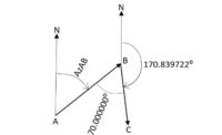
The following is the step-by-step procedure for calculating azimuth of line BC for the figure shown in Steps 1 through 4.
Step 1
Plan and prepare. Determine a known azimuth. In this case, it is shown to be 45 and the direction that the calculation will proceed (clockwise or counterclockwise). In this case, we are going to calculate clockwise from A to B to C. List the adjusted interior angle draw a sketch of the entire traverse. Be sure your sketch is reasonably accurate (that is, angles and distances should be close to scale). Label the points, the starting direction, and the interior angles. Orient the drawing properly to North.
 |
Step 2
Perform the calculation. Start by writing down the starting azimuth. Add 180° to obtain the back azimuth. Subtract the interior angle to obtain the azimuth of the next line. If the result is greater than 360, subtract 360. Write down the azimuth on the sketch.
Step 3
Repeat the calculation for each line of the traverse. That is, add 180° and subtract the interior angle.
 |
| EQUATION 2 |
Step 4
Check the calculations by using the last interior angle to recalculate the starting azimuth.
Example
For the figure below, calculate the direction of each line and provide a check. Proceed clockwise about this traverse. The calculations are shown in a tabular form for ease of understanding along with a sketch of the calculation of each line.
 |
| Azimuth of AB = Add 180° to get Back Azimuth ------------------------ Back Azimuth = Subtract Interior Angle ---------------------- The Azimuth of BC is 350°00' +180°00' --------- 530°00' -64°21' ------- 105°39' |
Calculation of the Direction of Line BC
 |
| Azimuth of BC = Add 180° to get Back Azimuth = --------------------- Back Azimuth = Subtract Interior Angle --------------------- The Azimuth of CD is 105°39' +180°00' --------- 285°39' -206°35' --------- 79°04' |
Calculation of the Direction of Line CD
 |
| Azimuth of CD = Add 180°00'to get Back Azimuth ------------------ Back Azimuth = Subtract Interior Angle ---------------------- The Azimuth of DE is 79°04' +180°00' -------- 259°04' -64°53' --------- 194°11' |
Calculation of the Direction of Line DE
 |
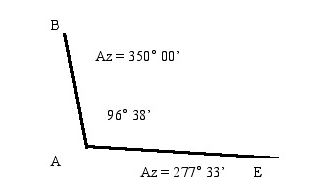
| Azimuth of DE = Add 180°00'to get Back Azimuth ------------------ Back Azimuth = Subtract Interior Angle ---------------------- The Azimuth of EA is 194°11' +180°00' -------- 374°11' -96°38' -------- 277°33' |
Calculation of the Direction of Line EA
 |
| Azimuth of EA = Add 180°00'to get Back Azimuth ------------------ Back Azimuth = Subtract Interior Angle ---------------------- The Azimuth of AB is 277°33' +180°00' -------- 457°33' -107°33' -------- 350°00' |
Calculation of the Direction of Line AB as a Check
Summary
That’s all there is to calculating azimuths. Simply follow a simple rule if going clockwise about the traverse: “Subtract the interior angle from the back azimuth of the previous course,” and the calculations can be performed quickly and easily. If bearings are needed, simply convert from azimuths to bearings as shown in the Table at the beginning. For those who aren’t using azimuths, I hope this article helps in understanding why many people now use azimuths.
This article was originally posted on www.pobonline.com.


