New Jersey Court Complex Renovated to Withstand Disasters
Frank J. Guarini Justice Complex in Jersey City is a $317.5-million design-build project that also faced “intricate structural challenges.”

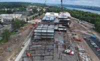
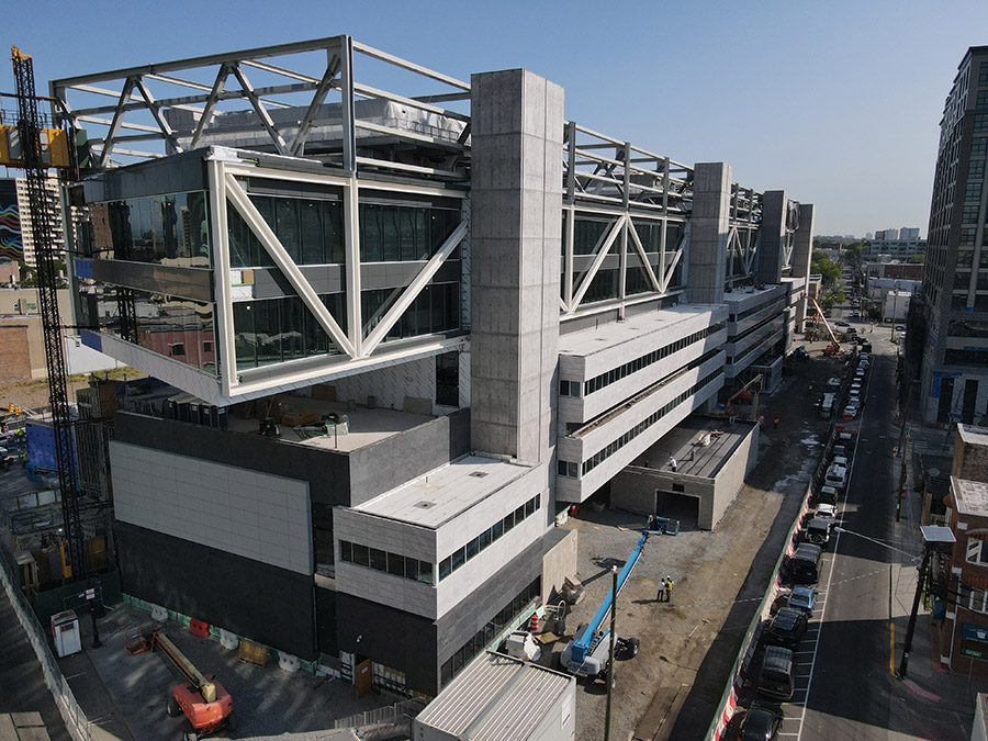
The Honorable Frank J. Guarini Justice Complex in Jersey City, N.J. is being constructed to withstand the blast from a terrorist explosion. A pair of massive steel trusses are designed to sustain the building’s upper floors in the event of such an attack.
Photo courtesy of Terminal Construction
While designing and installing a pair of massive steel trusses on the Frank J. Guarini Justice Complex in Jersey City, N.J. to sustain the building’s upper floors in the event of a terrorist explosion has no doubt tested the project team, the $317.5-million design-build renovation project also faces scheduling challenges.
The trusses spanning 700 ft apiece presented “intricate structural challenges” to create a modern building able to withstand catastrophic forces such as the explosion in the 1995 deadly bombing of the Alfred P. Murrah Federal Building Oklahoma City, says Liam J. McNamara, a senior associate for the project’s structural engineer, O’Donnell & Naccarato.
But since the project is being constructed as the design advances, McNamara says the design team issues construction sets and packages to assist with the schedule. For example, some of the earliest construction packages were issued before other team members were fully engaged on the project after it started in 2021.
“This means that we must work hand-in-hand with the contractors and architect to ensure proper allowances are provided to account for the completion of the design of the other trades,” McNamara said, “and, when required, make modifications of the structural design after issuance of these drawings to update for other design team advances.”
Approximately 85% complete, the project is within budget and scheduled to receive a temporary occupancy certificate by June, says Brian Senyk, vice president and chief engineer at Terminal Construction Corp., the project’s design-builder and general contractor.
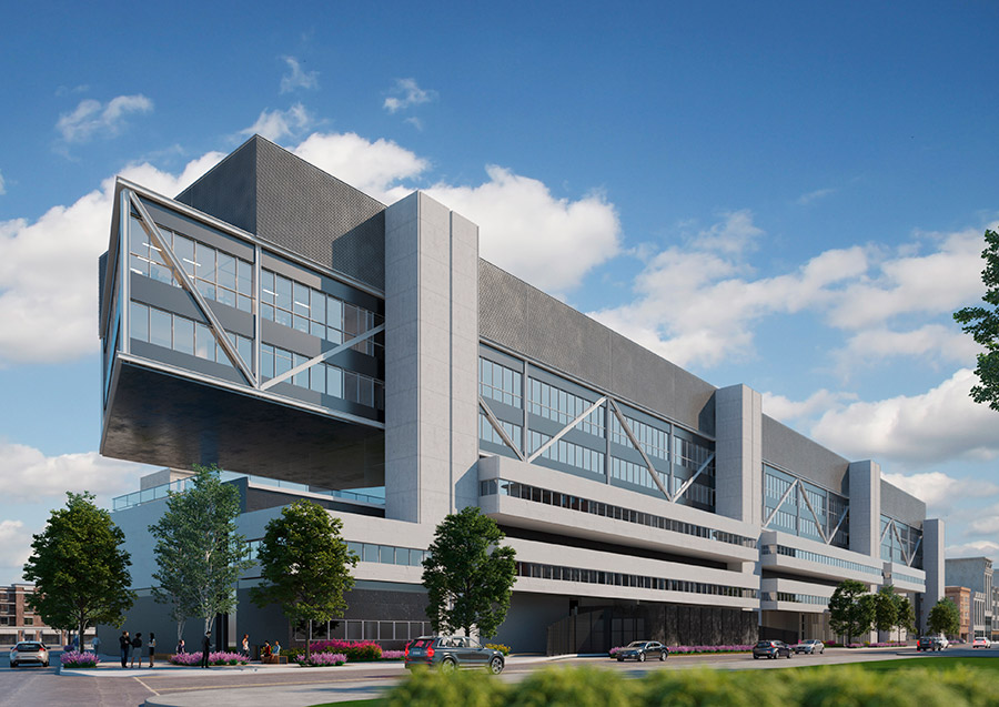
Approximately 85% complete, the $317.5 million courthouse is scheduled to receive a temporary occupancy certificate by June.
Rendering courtesy Terminal Construction
Top Hat Trusses
With two buildings and an adjoining six-story parking garage, the 405,000-sq-ft complex, named for a former Congressional representative of the area, is one of the state’s largest public revitalization efforts and will replace the Hudson County Administration Building, built in 1957.
There are two types of trusses on the building: a series of 15 “hat” trusses that span 85 ft to the two primary multi-story trusses at the north and south sides of the structure, which each span 700 ft, McNamara says.
The fourth and fifth floors, and the roof, are hung from the hat trusses and, in turn, the primary trusses. The exterior trusses, he says, are the primary gravity support for the upper half of the building and are supported by 11 concrete cores and three large concrete columns.
“No steel framing supports are continuous between the third and fourth floors,” McNamara says. “This creates large open courtrooms on the third floor, as it is largely free of vertical columns.”
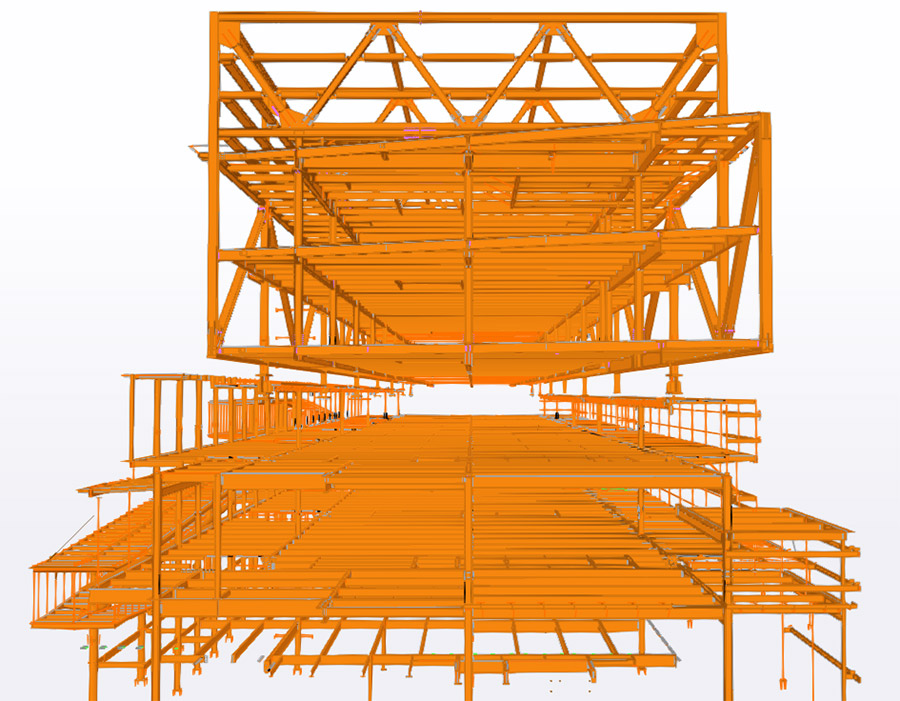
An excerpt from the BIM structural model shows the entire structure and the separation between the third and fourth floors.
Image courtesy Terminal Construction
Protective Design
Levels one through three are supported from foundations then columns and beams up to the third level.
Senyk says the structural and protective design is the project’s “most unique aspect.” He notes that the project includes a site-specific threat assessment report which detailed design-based threats (DBTs).
“The design of the structure and façade were required to accommodate these DBTs in terms of structural, blast, and ballistic performance,” he says. “Structurally, the design of the project essentially is two separate building.”
The fourth and fifth and roof levels are hung from roof top trusses, which Senyk says are in turn supported from larger trusses which run parallel with the length of the main building and rest on pairs of cast in place concrete shear towers which extend over 120ft above ground level.
The separation of the structure in this manner protects the overall building against progressive collapse, he says, as the top floors of the building would be protected against a threat impacting the lower three floors. The majority of the exterior façade is composed of curtain and window systems and portions of these systems were engineered to include ballistically rated glazing to project occupants and judges within the building.
The resulting installations, Senyk says, include glazing assemblies that are just under 3 inches thick and rated to stop rifle based ammunitions in accordance with Underwriters Laboratories (UL) standards.
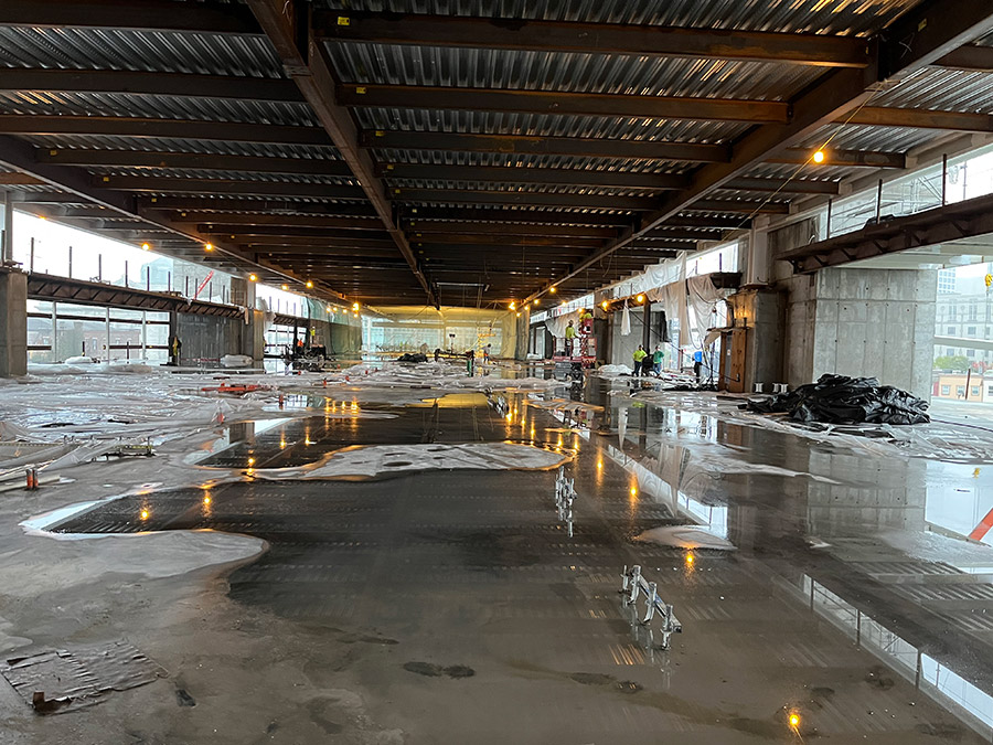
A third floor view shows the absence of columns between the third and fourth floors. Levels one through three are supported from foundations then columns and beams up to the third level.
Photo courtesy of Terminal Construction
Overcoming Challenges
The five-story primary courthouse building is a traditional steel framed building with a concrete slab and steel beams supported from steel columns down to the foundation for ground, second and third floors, McNamara says. The fourth and fifth floors as well as the roof deploy a similar floor system, but instead of being supported by columns, they are hung from the hat trusses and long-span exterior trusses.
Project site challenges include a high ground-water level requiring significant site dewatering and foundation rock anchors to hold down the uplift pressures due to groundwater; shallow depth to dense rock requiring rock excavation; and two existing archaic subterranean tunnels running below a portion of the building and parking garage requiring the foundations to span around the tunnels and be isolated from loading the tunnels.
There is a three-story enclosed pedestrian ramp between the courthouse administration buildings/entry lobby and the main courthouse building designed to maximize the views at the perimeter of the enclosure. The ramp is constructed from a center spine of vertical and sloped round HSS members with custom built-up steel plate framing members cantilevering to either side of the spine to create the floor and roof structures.

The entrance ramp is constructed from a center spine of vertical and sloped round HSS members with custom built-up steel plate framing members cantilevering to either side of the spine to create the floor and roof.
Photo courtesy of Terminal Construction.
Tunnel Vision
The presence of active tunnels and other infrastructure presented the design team with significant challenges.
Netta Architects design team worked with the parking structure that spanned existing Conrail and New Jersey Transit Corp. tunnels and was adjacent to an existing retaining wall along I-139 with limited space available for installation of deep foundation elements between and adjacent to the existing tunnels.
Netta used a detailed survey to match horizontal control of new deep foundation elements with existing tunnels in order to avoid potential conflicts, conducting a pre-construction condition assessment to document and photograph existing conditions of the tunnels and retaining wall, and enable evaluation of temporary protection for the existing retaining wall, as well as to secure approval from the agencies with jurisdiction, namely NJ Transit, New Jersey Dept. of Transportation and Conrail.
“Given the ambitious project schedule, it was critical that no delays or work stoppage occurred as a result of the foundation installation,” says Nicholas Netta, Netta Architects’ chief executive. “Having previously worked at NJ Transit, I understood the sensitive nature of these construction activities, and how they might impact the tunnels.”
Netta used a comprehensive construction monitoring program consisting of seismographs installed at adjacent structures and within the existing tunnels beneath the garage site. Threshold and limiting values for vibrations were established in accordance with the design criteria, NJ Transit, NJDOT and Conrail requirement and seismographs transmitted the data electronically through a wireless modem connection to a secure internet database, and instant notifications were transmitted via email in the event that threshold values are exceeded.
The parking garage construction was located over the top of two subterrain active rail tunnels, and Senyk says the project requirements dictated that no loads from the new garage could be imposed on the active tunnels.
The new garage would share foundations with the new courthouse, Senyk says, which was to be partially constructed above so a caisson foundation system was designed to accommodate and transfer the loads of the garage and courthouse building to a depth below the floor of the active rail tunnels.
However, the construction of these caissons could not produce vibrations over the threshold typically associated with historical restoration work or risk dislodging rock exposed within one of the rock bored tunnels, and to overcome the challenge, Senyk says the team installed vibration monitors, survey prisms, and cameras inside the tunnels—monitoring equipment that was used to ensure the caisson drilling operation did not exceed the prescribed vibration thresholds and threaten the operation of the active tunnel.
The five-story primary courthouse building is a traditional steel framed building with a concrete slab and steel beams supported from steel columns down to the foundation for the ground, second and third floors.
Photo courtesy of Terminal Construction.
Ramping Up
A glass enclosed ramp structure for pedestrian traffic from the ground floor to the second and third floors was supported by a 20-in. round steel tube structure independent from the main building structure, Senyk says, and ramp walkways were supported by custom built up box stringers which ran parallel to the walkway. These box stringers were then supported by WT steel sections cantilevered off the main tube structure, he says, and oriented perpendicular to the walkways.
The initial bridge design called for the mechanical equipment servicing the enclosed ramp to be located below the ramp walking surface within the void spaces between the box stringers and cantilevered WT sections. Finally, the bridge design called for each walkway to be independently enclosed within glass creating a singular glass tunnel from the ground floor to the third floor, Senyk says.
As the design progressed, more issues included ramp vibration; proper HVAC distribution within the ramp; and envelope stormwater drainage/runoff manifested, says Robert McNamara, principal and project manager at Netta Architects.
“In order to maintain the aesthetics of the iconic grand ramp entrance,” McNamara, “the entire design team needed to collaborate to generate practical design solutions to ensure that the ramp functioned as designed.”
The ramp envelope and supporting structural elements needed to be fully redesigned to satisfy vibration criteria; address building envelope thermal bridging issues; meet code required by HVAC condition; and resolve structural loading conditions, McNamara says. Numerous design meetings and brainstorming sessions were conducted with the bridging architect team to ensure all stakeholders were in alignment with the solutions.
“This was a wonderful example of the owner, bridging architect, general contractor and architect collectively working together to solve complex design issues without sacrificing the distinct contemporary look of the ramp,” McNamara says.

